Memdabad Road, Ahmedabad - 382445, Gujarat. sales@suryascientific.com

Our Location

Anhydrous HCI Gas Generator

Calcium Chloride Route

Working Principle

Hydrochloric acid and water form a maximum boiling point azeotrope at 11O°C corresponding to a concentration of 20.24%; (w/w) HCl. By adding concentrated CaCl solution to commercial hydrochloric acid the azeotrope 2 point is eliminated and the entire' HCl becomes available for liberation by distillation. Anhydrous HCl gas generation through Calcium Chloride Route is the most environmental friendly technique.

Process Description

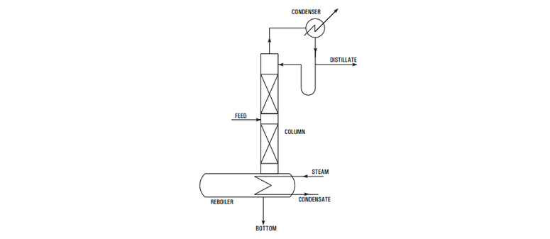
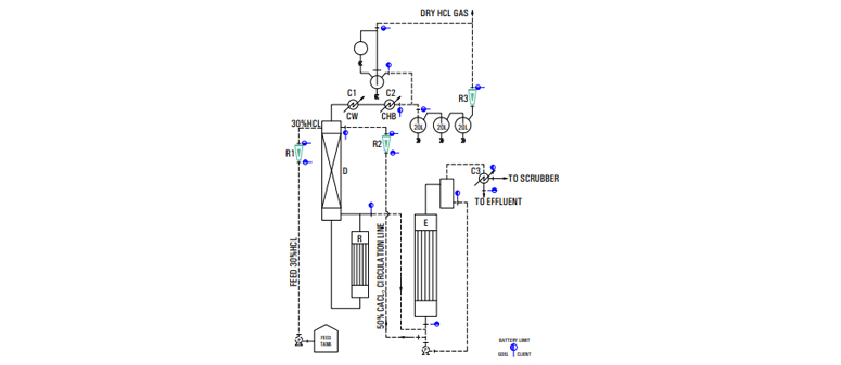
The above principle- is achieved in practice by feeding metered quantities of commercial HCl and 50% CaCl -solution to a stripping column with a steam 2 heated re-boiler at bottom. The effluent from bottom of the column is a dilute acidic calcium chloride solution which is concentrated to 50% in a evaporator and re-used. The vapor leaving is condensed stage wise with cooling water and chilled brine as coolant. The relatively dry gas passes through a mist eliminator and then through a rotameter to the point of consumption.

Raw material utility requirements

The indicative requirements for 20 Kg/hr HCl gas generator are given below

  • 30-32 % HCl, (Kg/hr) : 66
  • Cooling water at 30 °C (M /hr) : 4
  • Chilled brine at -10 °C (M /hr) : 3
  • Steam at 6 Kg/cm (g) : 150
LEGEND
R - REBOILER
D - COLUMN
E - EVAPORATOR
C1 - PRIMARY CONDENSER
C2 - SECONDARYCONDENSER
R1 - FEED HCL ROTAMETER
R2 - FEED CACL2 ROTAMETER
R3 - DRY HCL GAS ROTAMETER
CW - COOLING WATER
CHB - CHILLED BRINE
C3 - CONDENSER
P - PUMP

Continuous Distillation System

The limitations of batch distillations are naturally circumvented in continuous distillation as shown in fig.2 which is a typical fractionating unit comprising of ratification &stripping sections. Here feed is continuously fed to the column with withdrawal of top & bottom products. The process takes care on its own by simply maintaining the flow rates of feed & Utilities

However when more than two products are desired as in case of multicomponent systems additional columns are required as each column is capable of giving two products only. That is to say, for multicomponent system only one product is obtain in relatively pure form from each column. The other product containing the remaining components is fed to a subsequent column where again one product is obtained in relatively pure form. The addition of columns continue till the system becomes binary & both components are separated in the final column.

An important principle to be emphasized is that a total n-1 fractionators are required for complete separation of system of n components. Which of the two products in a column is to be obtained in relatively pure form depends on relative volatility of each component in the feed stock. For example consider a ternary solution consisting of a components A, B & C whose relative volatilities are in that order (A most volatile). In order to obtain three substances in substantially pure form either of the schemes shown in fig-3 may be used. Which of the two schemes would be used depends on the relative difficulties of separation in each method and the choice calls for finer considerations of principles of distillation. However scheme (b) is usually preferred since it requires one vaporization of substance A.